3D printing a full-size kayak
TL;DR - Converting 4.4 miles of PLA filiment into a usable kayak
Introduction
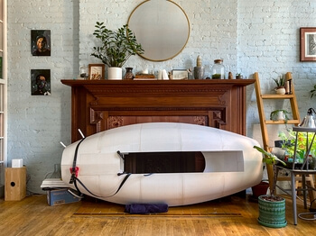
Well, I’m nearly two years behind on posting this, but anyway, here we are. I started this thing right at the beginning of “lockdown” and at the time we had just left our place in Manhattan for a lake house in Ohio. With ample space and views of water I began to mentally reprioritize my side-project backlog. It wasn’t long before I started dabbling with the idea of finally getting into 3D printing. I’ve worked with various additive manufacturing techniques in the past through work, but never on a hobby/personal level. I also wanted a kayak so I could explore the lake so it seemed like a good fit.
Design
Before I descended down yet another rabbit hole, I wanted to ensure I wouldn’t get too carried away. I have a pretty bad habit taking seemingly simple things like this and taking them to eleven. In order to avoid what I knew would be an inevitable outcome otherwise, I timeboxed the design to a single episode of The Office . This meant no CFD, no shape optimization of any kind, no nothing! The only other constraint was that it needed to be less than 10ft long so that I could store it vertically.
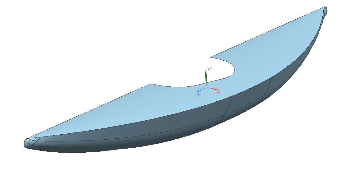
Even though it’s been a few years since my grubby fingers logged any serious CAD time, the muscle memory was still there. The twenty minutes I gave myself was more than plenty to finish the model. Before I started printing anything though, I wanted to run through a couple of sanity checks first.
Using the Python API in Blender, I wrote out a quick script that computed the water line at a given load. With this script I could then determine if my initial kayak design could at least maintain buoyancy with me in it (it could) and that it would sit roughly level in the water (pitch ≈ 0°). Next, I added a couple more details to the script and by looping across a range of heel angles I could generate the stability chart seen below.

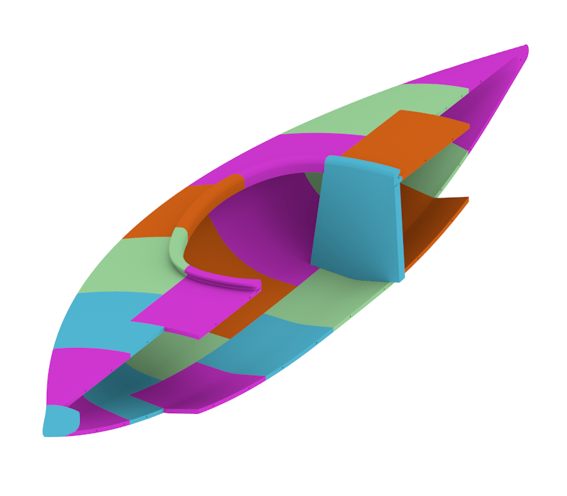
Now I know that it floats with me in it, and it’s stable, I could begin prepping the geometry for printing. Throughout the design phase, I had two areas that I was a little worried about. The first was in regards to stress concentrations developing at the joints between parts. To mitigate this as much as possible, I staggered the print cuts and increased infill density at specific locations. This ended up working really well. The other area I was concerned about was related to the print direction. Much like composites, a 3D printed part has a “ply orientation” which determines the structural response under loading. I’ve worked on a few aerodynamic components that require specific fiber orientations (think aeroelastic coupling) but 3D printed structures are a new medium for me. I figured the weakest link would be the bond strength between layers so all parts have been printed in a direction so as to minimize the largest force directly testing the layer adhesion.
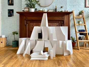
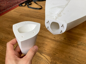
The cutaway below shows how I partitioned the kayak for printing. For reasons I’ll explain in the next section, my print volume was limited to a cube with edge lengths of 400mm. In total there were twenty-two separate pieces, of which fifteen were actually unique and the remaining seven were mirrored copies. Overall length is 9.2ft (2.8m).
The build
My initial strategy had been to try and print this thing in as few sections as possible using a printer I would build from scratch. I figured if I had a print volume that could handle parts up to around ~850mm on the longest side, then I could keep the total part count to under seven pieces. It’s at this point in the story that I really wished I could have stopped and pondered the question: could a longer print time increase the chance of a print failure? Unfortunately, I was drunk on the idea of building a giant printer and my smooth brain wasn’t having any of that…
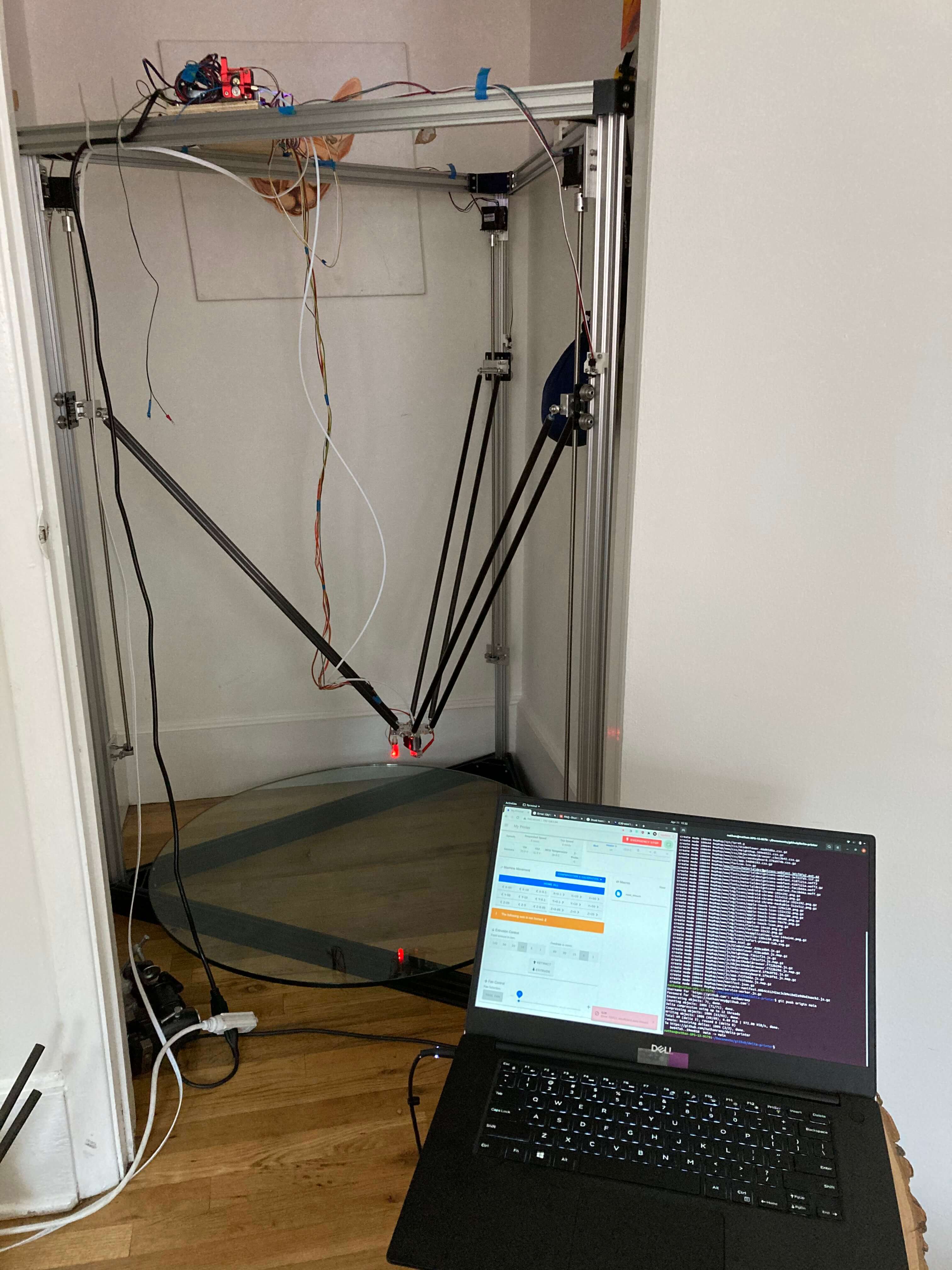
Anyway, I ended up building a delta printer with a cylindrical build volume of 1000mm in diameter and a height of 1000mm. It was big. REALLY BIG… The frame consisted of 2040 aluminum extrusions with half-inch diameter carbon tubes for the arms. Everything was controlled by a Duet 3 6HC running RepRapFirmware which I could interact with via the Duet Web Control running on my laptop. It was a good setup and surprisingly easy to get running. The only regret I had was using universal joint rod ends rather than magnetic ball ends. Although the universal joint ends were machined with a high tolerance and lubricated with heavy grease, they contained a non-zero amount of play. This small amount of play in the joints was amplified by the nearly 1.5m arms and ended up capping the top speed I could print at while still achieving a good quality finish. It wasn’t much of a speed limit, but for anyone thinking of building their own large-ish delta printer; make your life easier and just go for the magnetic ball ends instead.
With the printer built and presumably ready for printing, I proceeded to run through a couple of test prints. Turns out, actually assembling the printer and getting it moving is only about 5% of the total setup time (who would have thought!). The remaining 95% consists of a soul-sucking combination of A/B testing dozens of printer settings and depressed self reflection. Just one example went like this:
> The test prints have excessive stringing —> Ok, I need to optimize the filament retraction amount. There are two available settings: distance and speed. —> Oh wait, it's a Bowden style extruder with a 3m long feed tube... At these distances, it takes a non-trivial amount of time for any force on the drive side to propagate through the filament down to the print head! —> Why did I use a bowden style extruder?? Because I thought reducing sprung mass was actually important! (it's not...) —> Ok, fiddle with settings for another day or two. —> Contemplate swapping bowden extruder for a direct drive. —> More fiddling... —> Order a direct drive from the internet. In the meantime, bike to Brooklyn and machine the current effector plate so I can bolt on the new direct drive when it arrives. —> Direct drive gets delivered. —> Install direct drive and spend some more time fiddling with settings... —> Prints are now substantially less stringy. —> Move on to the next issue...
It might sound like I cherry-picked a particularly bad example above (and you’d be partially correct), but I encountered enough of these to really slow my momentum. Anyway, after spending waaay too long fiddling with various settings, I cut my losses and ordered a Creality CR6-Max and never looked back. Actually, I’ve been really happy with it so far. Print quality is roughly the same as the delta I built, however it’s far more consistent. It also requires almost no maintenance which is nice. I’ve since reconfigured the delta printer and it now lives on as a table that supports the CR6-Max…
 |  |  |
 |  |  |
 |  |  |
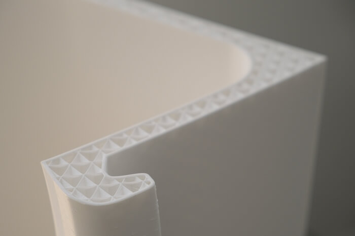
The total print time for all parts was 88 days, 21 hours and 44 minutes, with the longest part taking 7 days, 12 hours, and 20 minutes. Most parts required between two and five days to finish. All parts were printed at 40mm/s with no cooling and a cubic infill pattern which ranged in density from 12.5% up to 30% depending on location. A total of 46.5lbs (21.1kg) of PLA filament was used, which if lined end to end would stretch for 4.4 miles (7.08km).
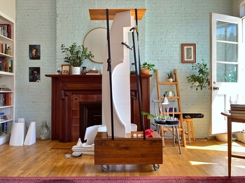
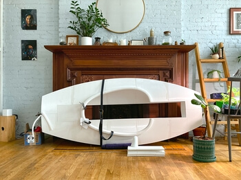
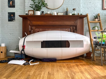
Parts were joined together using JB PlasticWeld two-part epoxy. To give the joints additional support (especially in tension) I cut down several M4 x 500mm stainless threaded rods into 50mm segments, which were then coated in epoxy and inserted at specific points along the part edges for additional strength. You can actually see the pins/holes in the progress pictures above as well as in the cutaway rendering.
Field testing
It’s now springtime, the weather is warm and the leaves are back out. I thought the easiest way to test the seaworthiness would be to just shoulder carry the kayak a half block east and take it for a quick spin in the Central Park Lake. Turns out that even though the lake is regularly full of people in rowboats, the clowns who run the NYC Parks department prefer that you don’t bring your own. This meant I got to walk across town and try again in the Hudson River.
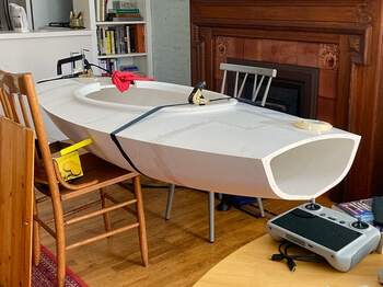
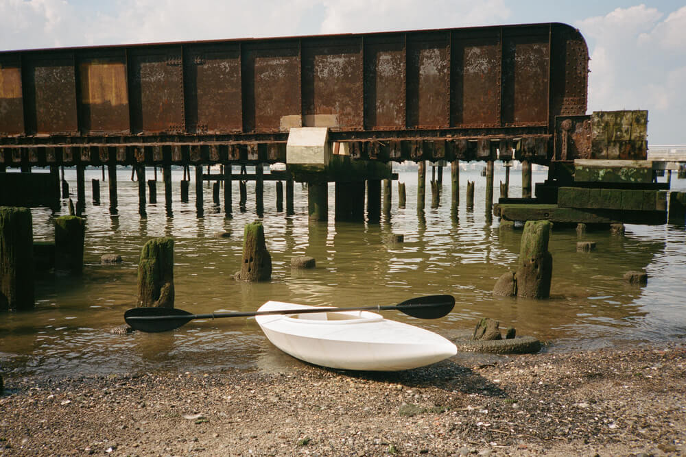
It was roughly a mile to the 69th Street Transfer Bridge and by the time I got there my shoulder was starting to get tired. Out of dumb luck, I happened to be there right at low tide which made things a little easier. At this point I was pretty sure that the epoxy joints would hold, but I was only 50/50 as to whether they would withstand the rougher waters of the Hudson. Standing precariously on the stone retaining wall I set the kayak down in the river. Loosely holding it in place, I watched the inside of the hull nervously half-expecting to see at least one small trickle of water appear. After about thirty seconds and no detectable leaks present it seemed there was only one last thing to do. With my hands on the coaming rim I hopped off the retaining wall and into the kayak. Gliding across the water, I waited in anticipation for anything indicating a catastrophic failure was imminent. Happily though, everything seemed solid and so eager not to get pushed back into the retaining wall by the waves, I paddled for deeper water.
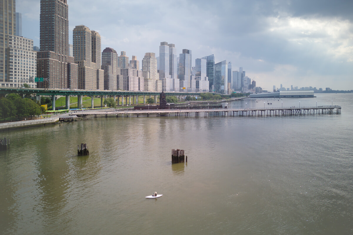
After an hour or so of paddling around everything seemed mostly fine. The roll stability was great and my buoyancy calculations were spot on. The hull did end up having a few small leaks which I could manage with a cup I had brought but nothing major. I also saw no bodies or severed limbs and only one needle which I consider a win.
Conclusion and next steps
My initial goal had been to simply print a kayak I could use to explore the lake with and maybe do some fishing. As time progressed though that eventually grew into circumnavigating Manhattan. Well, I ran short of time last year but I did get a chance however to take it out on a number of smaller trips. Actually, I’ve logged enough miles now that I don’t automatically assume it’s going to split in half when it hits the first boat wake. In fact, exploring the harbor has become almost as fun as bike exploring the city!
Although I’m genuinely pretty happy with how the kayak turned out, there are definitely some areas that could be refined. For starters, the kayak is right on the cusp of being statically unstable in yaw. It’s squirrely and handles like a white water kayak which I plan on damping out with a rudder. The surface finish is also rather rough, so I was thinking I would sand it down and apply some sort of marine gel coat for a nice smooth finish. Anyway, it’s currently March which means it will soon be warm enough to try that circumnavigation!